“인덕터 DCR 전류 검출 솔루션, 효율 높고 부품비 절약”
항상 사이클-대-사이클 피크 전류 제한·보호 제공
전원 시스템 매우 높은 효율·전력 밀도 달성 가능
■ DCR 전류 검출 기법 적용한 4-스위치 벅-부스트 컨트롤러
인덕터 DC 저항(DCR) 전류 검출 기법을 적용한 새로운 세대의 4-스위치 벅-부스트 컨트롤러를 활용하면 매우 높은 효율과 전력 밀도를 달성하는 전원 시스템 설계가 가능하다. 이 글에서는 기존 솔루션과 비교할 때 인덕터 DCR 전류 검출 솔루션의 이점에 대해 알아본다.
■ 4-스위치 벅-부스트 컨버터, 과전류·과전압 보호 사용
4-스위치 벅-부스트 컨버터는 입력 전압보다 높거나 낮거나, 혹은 같을 수도 있는 출력 전압을 발생하고자 할 때 인기 있고 잘 알려진 방법이다. 이 컨버터는 입력 단락 회로나 출력 단락 회로 같은 극단적인 결함 조건일 때 입력/출력(I/O)을 차단한다. 4-스위치 벅-부스트 컨버터는 배터리로 구동되는 기기나 차량용 시스템, 그리고 범용 산업 애플리케이션에서 과전류 및 과전압 보호와 함께 널리 사용된다.
■ 새로운 DCR 인덕터 전류 검출 기술
이전의 4-스위치 벅-부스트 컨트롤러는 전류 검출을 위해 외부 전류 검출 저항을 사용하는 데 반해, LTC7878은 인덕터 전류 검출을 위해 인덕터 DCR을 사용하도록 설계된 최초의 4-스위치 벅-부스트 컨트롤러이다.
이 디바이스는 새로운 피크 전류 모드 제어 방식을 사용해서, 레귤레이터가 벅 동작이든 부스트 동작이든 혹은 벅-부스트 동작이든 상관없이 사이클-대-사이클로 피크 전류 제한이 가능하다.
5V∼70V의 넓은 입력 전압 범위에 걸쳐 출력을 1% 정확도로 1V∼70V까지 레귤레이트 할 수 있다.
이 새로운 벅-부스트 컨버터는 전류 검출 저항을 사용할 필요가 없어 전력 손실을 없애고 솔루션 크기를 줄일 수 있다.
비싼 고전력 전류 검출 저항들이 필요치 않기 때문에 시스템 비용도 줄일 수 있다.
그럴 뿐만 아니라 인덕터 DCR 전류 검출이 지속적으로 인덕터 전류 정보를 제공함으로써 다위상 다중 IC 구성으로 통일된 피크 전류 모드 제어와 손쉬운 병렬 동작을 가능하게 한다.
■ 인덕터 전류 검출을 적용한 4-스위치 벅-부스트 컨버터

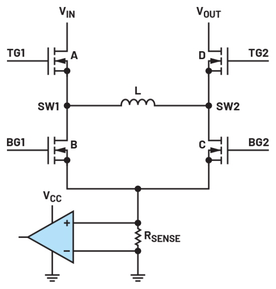
▲그림 1. 접지 레퍼런스 전류 검출을 적용한 4-스위치 벅-부스트 컨버터
많은 4-스위치 벅-부스트 컨트롤러들이 폐루프 작동을 위한 I/O 전류와 인덕터 전류를 검출하기 위해 2개 혹은 그 이상의 전류 검출 저항을 필요로 한다.
아나로그디바이스(Analog Devices)는 전류 모드 제어 루프에 사용되는 전류를 검출하는 데 한 개의 전류 검출 저항만을 필요로 하는 독창적인 벅-부스트 컨트롤러 제품들을 제공한다.
그림 1은 기존의 많은 제품에 사용되는 접지 레퍼런스 전류 검출 기법을 보여준다. 이 기법은 간단하며 IC 내부에 손쉽게 구현할 수 있다.
반면에 이 기법은 스위치 B나 스위치 C가 턴온할 때만 인덕터 전류를 검출할 수 있다.
이것은 각각 벅 구간일 때의 인덕터 밸리 전류이거나 부스트 구간일 때의 피크 전류이다. 두 MOSFET(B와 C)이 모두 전류 검출 저항에 연결되고 두 MOSFET을 서로 가깝게 배치해야 하기 때문에 PCB 레이아웃 옵션이 제한적이다.

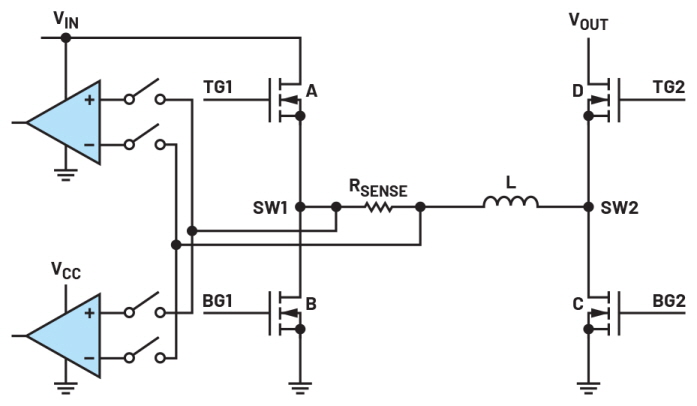
▲그림 2. 스위칭 노드 레퍼런스 전류 검출을 적용한 4-스위치 벅-부스트 컨버터
그림 2는 스위칭 노드 레퍼런스 전류 검출 기법을 적용한 또 다른 벅-부스트 컨트롤러를 보여준다.
전류 검출 저항이 인덕터와 직렬로 놓이기 때문에, 이 저항이 인덕터 전류를 지속적으로 검출할 수 있다.
스위치 A와 스위치 B가 턴온/턴오프할 때 스위칭 노드에서 이 검출 저항의 전압이 입력 전압과 접지 사이에서 위아래로 스윙한다.
따라서 공통 모드 잡음을 최소화하기 위해서는 전류 검출 회로가 공통 모드 제거비(common-mode rejection ratio, CMRR)가 매우 높아야 한다.
수십 볼트에 달하는 공통 모드 전압과 비교할 때, 검출되는 인덕터 전류 신호는 50mV∼100mV 대에 불과하므로 전원 스테이지 스위칭 동안 이 신호가 쉽게 왜곡될 수 있다.
이 잡음을 피하기 위해, 그림 2처럼 전류 비교기들을 차단하고 이들의 입력을 턴오프한다.
검출되는 신호가 연속적임에도 불구하고, 짧은 블랭킹 시간으로 인해서 짧은 시간 동안 인덕터 전류 정보를 이용하지 못한다.

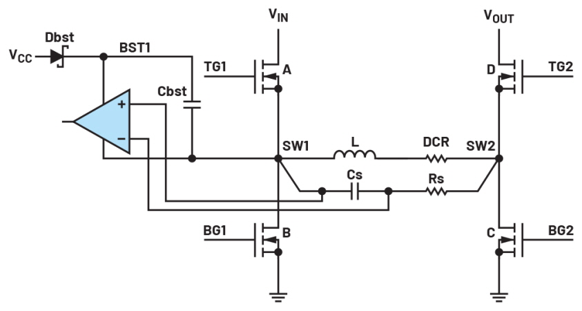
▲그림 3. 인덕터 DCR 전류 검출을 적용한 4-스위치 벅-부스트 컨버터
그림 3은 LTC7878에 적용된 인덕터 DCR 전류 검출 기법을 보여준다.
RC 검출 네트워크의 시간 상수를 인덕턴스 및 DCR과 매칭함으로써(L/DCR = Rs x Cs), 인덕터 전류가 검출 네트워크(Cs) 상에서 전압 신호로 변환되며, 이득은 인덕터의 DCR이다.
BST1/SW1 회로 아래 쪽에 전류 비교기가 설계되어 있는데, 이는 작동하는 동안 VIN-GND 스위칭 노드에 따라서 스윙한다.
전류 비교기와 스위칭 노드 상의 동일한 공통 모드 전압 때문에, SW1이 스위칭할 때 전류 비교기 입력을 DCR 검출 신호로부터 차단하지 않아도 된다.
이와 같은 방법으로 인덕터 전류를 사이클-대-사이클로 레귤레이트하고 지속적으로 제한한다.
스위칭 노드 레퍼런스 전류 검출 기법과 비교하면, BST1/SW1 아래에 단 한 개의 비교기만 요구된다.
뿐만 아니라 다양한 DCR 값을 지원하고 다양한 인덕터를 사용하는 것이 가능하다.
DCR이 낮은 인덕터 같은 경우에는 ISNSD 핀을 설정해서 신호를 증폭하고 신호대 잡음비(SNR)를 보통의 DCR 검출 기법보다 4배 더 높게 향상시킬 수 있다.
이 같이 높은 SNR 설계는 시스템 신뢰성을 크게 향상시키고 다양한 듀티 사이클에 걸쳐서 안정적인 스위칭 동작을 달성한다.
■ 다위상 병렬 동작
인덕터 DCR 전류 검출과 함께 연속적인 인덕터 전류 정보를 이용할 수 있기 때문에 통일된 피크 전류 모드 제어 회로를 LTC7878에 구현할 수 있다.
이는 많은 피크 전류 모드 벅 또는 부스트 DC-DC 컨트롤러와 마찬가지로, 다위상 동작을 가능하게 한다.
모든 ITH 핀들을 공유하고 모든 CLKOUT 핀들을 데이지 체인으로 연결하는 방법으로, 여러 LTC7878 디바이스를 병렬로 연결해서 부하에 더 많은 전류를 제공할 수 있다.
모든 채널들에 걸쳐서 부하 전류를 고르게 분배하고, 인덕터들 간에 전류를 공유함으로써, 열 평형과 높은 효율을 보장한다.
ADI 고유의 사이클-대-사이클 인덕터 전류 공유가 스타트업과 부하 트랜션트 시 인덕터들의 과전류 스트레스를 낮춤으로써 시스템 신뢰성을 높인다.
■ 그 밖의 특징
스위칭 주파수를 100kHz∼600kHz로 프로그램할 수 있으며 또는 외부 클럭에 동기화할 수도 있다.
내장된 7V NMOS 게이트 드라이버는 로직 레벨 또는 비-로직 레벨 MOSFET을 구동할 수 있다.
그 밖에 다른 특징으로는 지능적인 외부 VCC 바이어스 핀, PGOOD 지시기 핀, 그리고 서로 다른 전류 한계 설정을 통해 선택 가능한 불연속 전도 모드/연속 전도 모드(DCM/CCM) 동작을 들 수 있다.
LTC7878은 최대 70V의 입력에 사용될 수 있고, 출력은 1V∼70V로 프로그램할 수 있으며, 5 x 5mm QFN 패키지로 제공된다.
■ 맺음말
LTC7878은 인덕터 DCR 전류 검출을 적용한 고성능 4-스위치 벅-부스트 컨트롤러이다. 벅, 부스트, 벅-부스트 구간에서 피크 전류 모드 제어를 사용하고, 항상 사이클-대-사이클 피크 전류 제한과 보호를 제공한다.
인덕터 DCR 전류 검출을 사용해서 높은 효율을 달성하고 부품 비용을 줄이도록 한다. 더 높은 전력을 제공하기 위해 다위상 아키텍처로 여러 디바이스를 손쉽게 병렬로 연결할 수 있다.
###
※ 저자 소개
슈 장(Xu Zhang)은 중국 베이징의 칭화 대학에서 2000년과 2003년에 각각 전기공학 학사학위와 석사학위를 취득했다. 2009년에는 미국 콜로라도주 볼더에 위치한 콜로라도 대학 - 볼더 캠퍼스에서 전기공학 박사학위를 취득했다. 2010년에 아나로그디바이스(Analog Devices)에 입사해서 고전압 고전력 차지 펌프 컨트롤러, 스위치드 커패시터를 적용한 혁신적인 하이브리드 벅 컨트롤러, 양방향 벅 컨트롤러, 4-스위치 벅-부스트 컨트롤러를 비롯한 다수의 업계 최초 전원 컨트롤러 IC를 설계했다. 현재는 전원 컨트롤러 그룹을 이끌고 있으며, 고성능 실리콘 기반 전원 레귤레이터 및 컨트롤러 개발을 책임지고 있다.


